DFM Design Guide · 01
The minimum wall thickness is set by the weakest stage of the process chain - not by the sintered material's final strength.
Wall-Thickness Design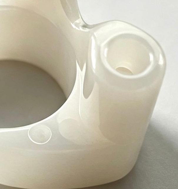
01-A · Minimum Wall-Thickness Boundary
| Feature | Value | Grade |
|---|---|---|
| Connecting wall (significant adjacent thickness difference) | ≥ 1.2mm | Recommended |
| General structural wall, no impact load | ≥ 0.8mm | Conditional - closed cross-section preferred |
| Decorative thin edge, no load | ≥ 0.3mm | Limited use |
| Thin wall under impact load | Needs DFM review | Needs evaluation |
The 1.2mm connecting-wall rule is not fundamentally a strength requirement - it's stress-concentration control. When adjacent wall-thickness ratio exceeds 1.5:1, that's a warning; past 2:1, the sintering-shrinkage mismatch at the thick/thin boundary concentrates stress, and warping or fracture risk rises sharply. For thin walls under impact loading, closed cross-sections (round or oval tubes) are noticeably more reliable than open cross-sections (C- or U-shapes).
01-B · Wall-Thickness Ratio & Sink-Mark Risk
Past a 1:1.5 wall-thickness ratio, the sink mark is invisible before sintering - by the time you see it, it's already a finished part
1:1.5 is the safe ceiling for the thickness ratio between adjacent features. Plastic injection molding can partly compensate for sink marks through packing pressure - ceramic sintering has no such compensation mechanism. Once a part enters sintering, the sink mark is irreversible.
| Wall-Thickness Ratio | Risk Band | Action |
|---|---|---|
| < 1:1.5 | Safe zone | No special treatment needed |
| 1:1.5 - 1:2 | Caution zone | Add a fillet or chamfer at the thick/thin transition |
| > 1:2 | High risk | Mandatory DFM review; redesign recommended |
Failure Scenario
Sample passed visual inspection and initial measurement. Two weeks later, at the customer's assembly stage, a sink mark appeared on the cosmetic face. It wasn't there in the green state, wasn't there after debinding - it only appeared after sintering, by which point there was no way to fix it.Three-step physical mechanism:Step 1 (green state): binder fills the body like a layer of snow, masking every irregularity - what you see is a flat surface.Step 2 (debinding): binder vaporizes, pores appear, the thick region's internal porosity is far higher than the thin region's, but the outer shape still holds.Step 3 (sintering): pores collapse, the thick region shrinks far more than the thin region, the surface caves inward - the sink mark becomes visible and irreversible.
01-C · Root Fillets
The root fillet is an engineering formula, not a cosmetic suggestion
Rule: R ≥ 0.5 × t (t = local wall thickness). General recommendation R ≥ 0.5×t, absolute minimum R > 0.25mm. Example: 2mm wall → R ≥ 1.0mm; 1mm wall → R ≥ 0.5mm.
This R ≥ 0.5×t figure comes from real engineering observation of sintering-stress distribution, and is stricter than typical plastic-injection fillet recommendations - ceramic sintering stress cannot be relieved by post-processing, only dispersed in advance through geometry.