DFM Design Guide · 02
±0.05mm is the output of four conditions being met simultaneously - change any one condition and the achievable precision changes with it.
Tolerance & Dimensioning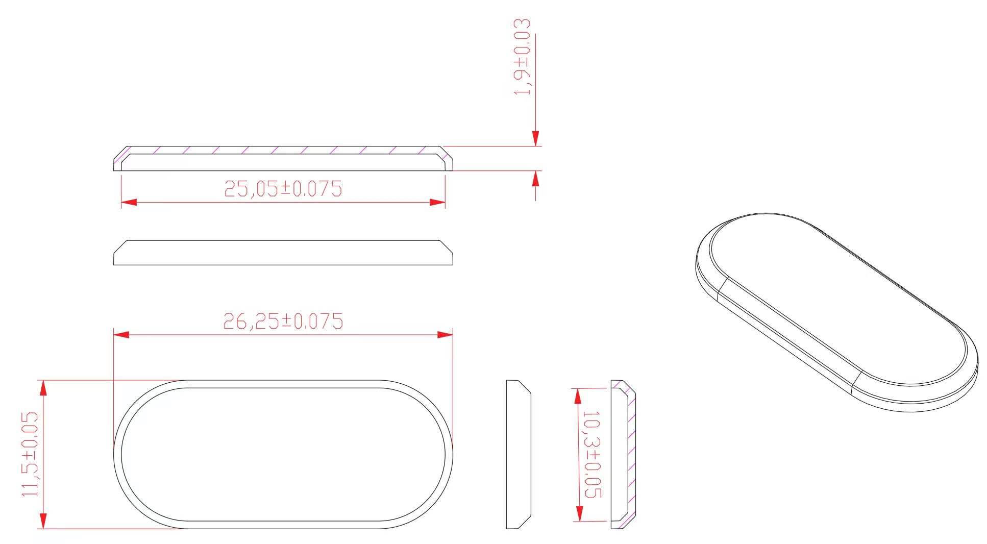
02-A · Tolerance Capability Boundary
| Condition | Achievable Tolerance | Grade |
|---|---|---|
| Single color · local feature <20mm · uniform wall thickness | ±0.05mm | Stably achievable |
| Single color · overall span dimension (housing 27-40mm) | ±0.10-0.15mm | Negotiable / may need CNC |
| Dual-color shared mold (black + white, one tool) | ±0.4% | Tolerance degrades |
| Critical dimension in non-uniform wall region | Case-by-case | Needs DFM review |
The most common spec-sheet mistake: marking every dimension ±0.05mm uniformly. Real assembly-critical dimensions needing ±0.05mm are usually only 1-3 per part. Relaxing everything else to ±0.1mm doesn't hurt function, and substantially improves yield and cost.
Failure Scenario
The technical specification required ±0.05mm for all critical dimensions. We met this in the prototype stage by accepting lower yields and longer cycle times. But in mass production, dimensions which is bigger than 27mm, consistently drifted to a ±0.10–±0.15mm tolerance band. Rework or specification revision was then required, which delayed the project.02-B · The Dual-Color Shared-Mold Trap
Black and white must be tooled separately - this is a physical constraint, not a supplier upsell
Root cause: black zirconia's colorant mechanism changes the powder's sintering behavior, producing a systematic difference in linear shrinkage versus white zirconia. A mold designed against one shrinkage rate will always leave the other color systematically off-dimension.
| Approach | Result | Grade |
|---|---|---|
| Black and white tooled independently | ±0.05mm | Standard, recommended |
| Black and white share one mold | ±0.4% | Only for ≥±0.1mm tolerance needs |
At equal geometric volume, the black version weighs about 8-10% more than the white version. If your product has a weight spec, both color versions need it stated separately.
Two SKUs (black + white) shared a mold. Black samples came out 0.08mm oversize on the mating dimension, white was fine. Retuning the mold undersized the white part instead. The two colors could never pass together.
02-C · Drawing Information Requirements
Common problems: 2D and 3D dimensions disagree (3.5mm vs 3.45mm) → mold scale-up factor can't be determined; cosmetic-face grade not marked → gate location can't be determined, overall mold design direction unclear; uniform ±0.05mm across the whole drawing → yield drops substantially with no engineering benefit.
- 3D model (STEP/IGS), matching the 2D drawing's dimensions
- 2D drawing with tiered tolerance callouts (critical / standard / reference)
- Cosmetic-face grade marked (A-grade / B-grade areas clearly identified)
- Material color confirmed (black and white submitted separately)
- Functional test requirements (impact / wear / corrosion, if applicable)