Whitepapers · 04
Why does ceramic drop-test failure almost always start at a corner - and how do you design around it?
WP-04 · Corner Design & Drop ReliabilityI · Background
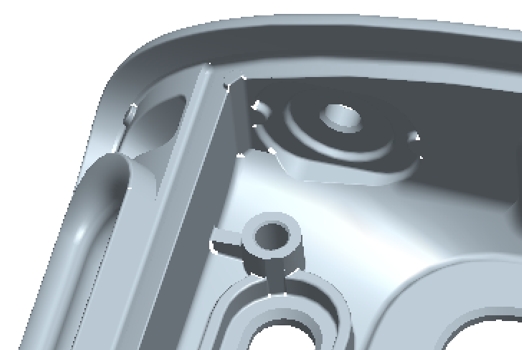
The product has assembly through-holes, locating/mounting profiles, corners, and non-uniform wall thickness. This paper focuses on the reliability difference driven by corner-design changes.
II · Failure Scenario
Parts sintered and polished looked cosmetically fine, but in drum-drop testing, pre-design-change samples showed clear corner cracking. Every crack location on the dropped parts corresponded exactly to a red highlighted weld point in the Moldflow analysis - the injection weld location.
III · Root Cause - Two Risks Stacked
Corners sit at the intersection of two independent risks: a weld-line location and a stress-concentration point. These two independent risks stack, making the corner the weakest region of the entire part. The weld points Moldflow predicted and the crack locations seen in drum testing line up exactly.
IV · Solution
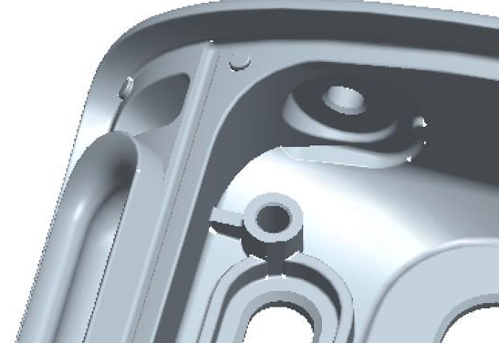
Given the internal assembly space constraints, a fillet radius was added at the corner - doing two things at once: increasing local thickness, and shifting the weld location away from the corner into a lower-stress zone. Where space allows, symmetric corners should get the same fillet treatment too, not just the one observed to fail.
V · Verification Result
Repeat drum-drop testing after the design change: corner cracking dropped by 80%.
VI ·Comparison before and after optimization
In an independent third-party drum test, a design without corner optimization (internal corners prone to cracking under impact) was compared under identical conditions with our optimized corner design (internal corner fillets, projected strain held under 0.3% via FEA simulation). The unoptimized design's failure rate: 100%. Our optimized design's failure rate: roughly 50% - a real reduction by half, but honestly, not yet at a production-acceptable stability level. We're stating that plainly here, not overstating it as "solved."
Independent Corroboration
Failure location analysis validated our core conclusion: in the non-optimized design, crack propagation began at the internal corner—exactly matching the 'corner cracking'failure mode we documented in our quality diagnostics.VII · Quantified Corner-Fillet Rule
General recommendation: R ≥ 0.5 × t (t = local wall thickness).This matches the fillet rule published on the DFM Wall-Thickness page: internal corners and wall-thickness transitions need R ≥ 0.5×t, external corners need R ≥ 1.5×t. Sharp corners impede feedstock flow and interrupt pressure transfer, so the thick region can't get continuous packing compensation - directly producing a surface sink markApplied to corner cracking, the same fillet logic carries the added benefit of relocating the weld line.
VIII · Fracture-Toughness Fundamentals
| Material | KIC |
|---|---|
| Y-TZP Zirconia | 8-10 MPa·m¹/² |
| Alumina | 3-4.5 MPa·m¹/² |
| Stainless Steel (reference) | 50-100 MPa·m¹/² |
IX · Design Rules
- If a corner is also a weld-line location, the risks stack - treat it as top priority
- Corner fillets aren't just cosmetic or generic stress relief - in ceramic CIM they also actively relocate the weld line
- When feasible, use FEA to hold projected corner strain under 0.3% — more reliable than applying a rule-of-thumb formula alone
- Use Moldflow at the DFM stage to predict weld location, and design it away from corners and wall-thickness transitions up front — don't wait for drop-test failure to react
PROJECT CTA
Does this apply to your project? If your design is running into a similar issue, send us your design files or describe your application — we'll give you a clear judgment within 3 business days.