Whitepapers · 06
For wireless-connected device housings, why does ceramic have a real, measurable RF-performance advantage over metal?
WP-06 · Material Selection for Wireless-Connected Devices: Ceramic's RF AdvantageI · The Core Question
A metal housing shields radio signal - basic electromagnetics. But how large that shielding effect really is, in practice, is rarely answered with real numbers. We obtained a set of independent third-party lab measurements that answer it concretely.
II · Measured Data - Ceramic Outperforms Metal by 4-6dB
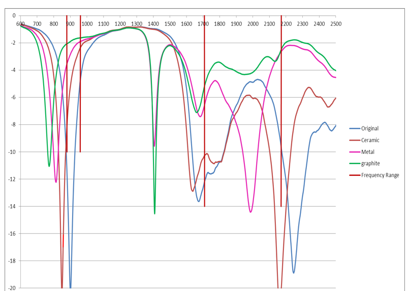
In a third-party test of one wireless-connected device, the same product was built in both a ceramic housing and a metal housing version, and TRP (Total Radiated Power) and TIS (Total Isotropic Sensitivity) were each measured at two independent labs. In the test, the ceramic housing measured roughly 3.2–5.4 dBm TRP and -84 to -88 dBm TIS, consistent across two independent labs; the metal housing measured roughly -1.2 to 0.9 dBm TRP and -79.7 to -82 dBm TIS.Converted, the ceramic housing's antenna performance was roughly 4–6dB higher than the metal housing's — not a small number in wireless communication, a genuine signal-strength and receive-sensitivity advantage. And this comes from cross-validation across two independent labs, not a single test's coincidence.
III · Mechanism - Why Ceramic Is RF-Transparent and Metal Isn't
Metal is an electrical conductor; electromagnetic waves can't pass through a conductor's surface (skin effect) — they get reflected at the metal skin, which is the physical reason a metal housing inherently shields an internal antenna's signal, regardless of how finely the housing is engineered. That shielding can only be locally worked around with slots or gaps — which then compromises water resistance, structural strength, or other properties. Ceramic (zirconia, alumina) is a dielectric material — non-conductive, and electromagnetic waves pass through it directly with almost no shielding loss. That's why ceramic housings clearly outperform metal on antenna performance — not because ceramic is "better suited" to wireless devices, but because dielectric materials are naturally "transparent" to RF signal.
IV · Supporting Data - Dielectric Constant & Loss Tangent
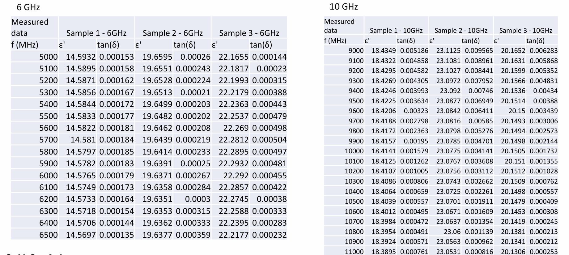
At 6GHz and 10GHz, we measured dielectric constant (ε') and loss tangent (tan δ) on three zirconia formulations with different yttria-doping ratios: dielectric constants spanned 14.5–23.2, loss tangent in 10⁻⁴ to 10⁻³ range — low loss tangent means less signal energy lost passing through the material, better for RF transmission. The measurable difference among the three samples shows yttria-doping ratio is a real, usable engineering variable for tuning dielectric performance.
V · An Honest Boundary
This data comes from one real third-party product test, not an experiment we designed specifically to prove this point — so the test conditions (specific frequency band, specific product structure) aren't ones we could freely choose or reproduce. The dielectric-constant data is our own material measurement, but a quantitative relationship between yttria-doping ratio and dielectric performance isn't yet a complete design rule — it's a real, valuable observation, not yet a directly applicable engineering formula.
VI · Design Rules
- Wireless-connected devices (Bluetooth earbuds, smartwatches, wireless locks, industrial wireless sensors, etc.) with clear signal-strength or receive-sensitivity requirements get a real, measurable RF advantage from ceramic housings over metal
- This advantage doesn't require extra structural design (metal housings need slotted antenna windows) — a ceramic housing can be a single molded piece, potentially simplifying structure instead
- Yttria-doping and other formulation levers can tune dielectric performance within a range; the quantitative relationship still needs more data
- This selection logic should be weighed together with the other dimensions in the Material Selection Framework (thermal conductivity, wear resistance, cost) — not an isolated decision criterion
PROJECT CTA
Does this apply to your project? If your design is running into a similar issue, send us your design files or describe your application — we'll give you a clear judgment within 3 business days.