DFM Design Guide · 04
Green-body strength at demolding is far below the sintered finished part's - what you think of as "hard ceramic" behaves like a wet sand structure at that moment.
Undercuts & Demolding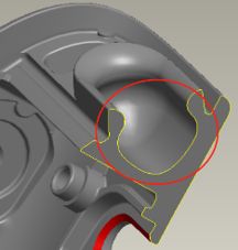
Failure Scenario
Two small undercuts on the side of the part were successfully demolded by forced ejection during the plastic injection molding trial. However, when the process was switched to ceramic CIM for the first pilot production run, both undercuts fractured at the root upon demolding.Three Layers of Risk, Stacked
Mechanical tearing stress at demolding; sintering-shrinkage stress concentrating at the undercut geometry; if a thin wall is also present nearby, the two concentration points combine and fracture probability becomes incomparable to plastic.
Three Resolution Paths
| Path | Best For | Trade-off |
|---|---|---|
| Redesign, eliminate the undercut | Undercut in a non-critical functional area | Lowest production cost |
| Side slider | Undercut is functionally required; hole diameter ≥0.3mm | Mold cost increases |
| CNC post-machining | Shallow undercut, customer accepts post-processing cost | Fast tool wear on ceramic hardness |
Hole geometry reference: blind-hole depth-to-diameter ratio ≤1.5:1 (beyond this, debinding collapse risk rises); through-hole depth-to-diameter ratio ≤3:1 (beyond this, ejector pins break easily); hole diameter recommended ≥0.3mm - extreme ratios need dedicated DFM confirmation. The 5.2:1 case-study value describes an open cavity formed with a removable core, so these hole-ratio limits do not apply to it.