Part Type
Thick-wall alumina, complex structureWhitepapers · 05
Why do open-frame structures always warp toward the gate side after CIM sintering - and how did three independent gate-plan iterations take yield from 0% to 100%?
WP-05 · A Three-Round Gate-Iteration Study in CIM Distortion ControlProblem
Open-frame warpage, yield 0%yield, flatness 0.019mmFinal Result
100%yield, flatness 0.019mmVerification
Moldflow + Short-shot + OGP + CTI · Background & Problem Definition
A structurally complex, thick-wall alumina part: dense thin ribs in the middle, a 4.8:1 wall-thickness ratio, and a fully unconstrained open-frame structure at the far end. Ceramic CIM feedstock, once heated, isn't a simple liquid — it's a slurry that thickens as it flows, with solid loading of 50–55% and pronounced shear-thickening behavior. The farther the flow travels, the slower and thinner it runs; this part pushed that property to its limit — a long flow path, five 1mm-wide cooling-fin ribs crowding the middle, and a fully unsupported open end. Alumina sinters to HV1600, too hard to correct by grinding — any green-body density unevenness gets amplified 3–5× through debinding and 1600°C sintering into irreversible warpage and micro-cracks.
II · Round 1 - Single Gate, Single-Side Feed: Failed
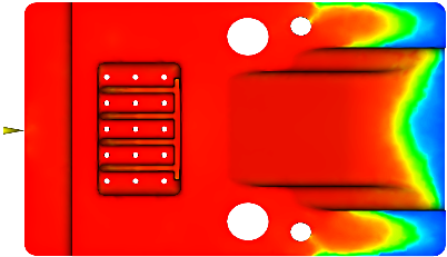
Design: a single side gate at one end's thick wall, centered for symmetric fill, meant to reduce feedstock hold-up in the high-flow-resistance rib zone while simplifying the tool and revealing the part's native flow pattern.
Simulation & short-shot: a 762,096-element 3D Moldflow model showed flow advancing linearly along the long axis, badly obstructed at the rib zone, and splitting toward both non-rib ends — leaving a low-density flow-starved zone in the middle. Green density showed a one-sided gradient, lowest exactly at the open-frame region. Physical short-shots matched: fast fill at the thick end, a cliff-edge slowdown through the ribs, and a low fill fraction reaching the far open end.
Production Result — 100 Parts
All 100 parts showed distortion: max inward warp of 0.176mm at the far open-frame end (far past the ±0.05mm limit); 100 parts showed visible sink marks on the far sidewall; 100 parts showed CT-detected weld micro-cracks; overall dimensional yield: 0%.Root cause: a single-direction flow path that's too long bleeds pressure continuously, leaving the far-gate end under-dense. Combined with an unconstrained open structure, the low/high density shrinkage mismatch has nothing to cancel it against, producing inward warpage.
III · Round 2 - Three Gates, Single-Side Feed: Partial Success
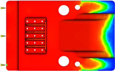
Design: kept single-side feeding, upgraded to three independent submarine gates spaced along the same thick-wall edge — two outer gates routed around the dense rib zone, one center gate feeding directly through it, aiming to shorten each flow path and cut pressure loss.
Result: yield rose to 84%, warpage much reduced, but not solved — flow was smoother, yet the lowest-density point remained at the same far open-frame sidewall. Shortening flow distance and easing local resistance didn't change the underlying single-direction flow logic; the far end stayed the pressure tail and lowest-density zone.
IV · Round 3 - Single Gate, Three-Face Feed: The Final Solution
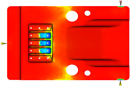
Design: abandoned the single-side multi-gate layout entirely. A single injection source split into three feeds entering from the left, right, and back faces simultaneously, converging toward the part's center — deliberately relocating the low-density meeting zone to the central, non-load-bearing rib area, which carries no sealing or assembly function.
Moldflow simulation predicts flow path and density distribution ahead of molding, cross-checked against physical short-shot trials. OGP optical measurement performs full-dimension batch inspection. Full CT inspection confirms no internal micro-cracks, voids, or density anomalies. Four methods cross-verify each other - no conclusion rests on a single inspection technique.
Production Result — 200-Piece Batch
Max warpage at the far open frame: 0.019mm, far under the ±0.05mm requirement; full CT inspection found no internal micro-cracks; overall yield: 100%.SOURCE: OGP + FULL CT INSPECTION · 200-PIECE PRODUCTION LOTV · Iteration Summary
| Round | Approach | Finding |
|---|---|---|
| 1 | Single gate, single-side feed | Confirms the core problem: far-end low density + open-frame warpage; flow path too long, density gradient too steep |
| 2 | Three gates, single-side feed | Eases local flow distance/resistance; doesn't change single-direction flow, low-density location unchanged |
| 3 | Single gate, three-face feed | Changes flow direction entirely - outer-to-center convergence relocates the low-density defect to a non-functional zone |
Three iterations meant three full injection-debinding-sintering-inspection cycles - each round took one to two weeks to know the result, not something solvable by dozens of desktop simulation attempts. Every attempt carried real time and material cost. That's why, when the third round finally took yield from 0% to 100%, that number was never just a statistic to us.
VI · Conclusion & Design Rules
- Both single-direction feed approaches (one gate or three gates, same side) failed to solve far-end open-frame warpage — one badly out of tolerance, the other only partially improved
- The dense central rib zone is the dominant flow-resistance source — regardless of gate count, flow through it on one side produces uncontrollable turbulence
- Single-gate, three-face centripetal feed is the optimal approach — one injection point preserves flow consistency while relocating the low-density convergence zone to a non-load-bearing area
- Alumina CIM gate design needs to move past single-side-feed plastic-injection thinking, and target green-body density distribution as the primary design objective — not just shortest fill time
- This approach transfers directly to similar precision structural parts
VII · Verification System
PROJECT CTA
Does this apply to your project? If your design is running into a similar issue, send us your design files or describe your application — we'll give you a clear judgment within 3 business days.